Custom Winding
Custom Winding
This feature allows to totally customize the winding arrangement of the magnetic
To access the custom winding click on: Winding tab

And access the winding screen: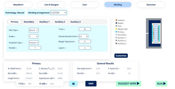
Before using the custom winding, all winding parameters must be determined, it means that all inputs of the windings must be fulfilled, and by clicking on run, the outputs are generated.
Custom winding needs 4 parameters to customize the winding arrangement.
- The windings. Primary, Secondary, Secondary 2, Auxiliary 1 etc
- The number of magnetic turns of each winding

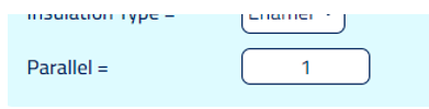
- The number of parallels on each winding
- The number of layers in each winding

Once these 4 parameters are fulfilled the advance customization can be done.
For doing so the “Customize” button has to be clicked.

And the custom winding interface will be opened:

6 actions can be done in this mode:
 Drag and Move Layers:

 Connect layers
 Determine the number of parallels and turns per parallel of the layer


 See how the new arrangement would look on the window of the magnetic

 Apply Changes so the changes are implemented and the simulation is ran. It returns to the winding screen


 Reset to the last Apply Changes configuration


How it works?
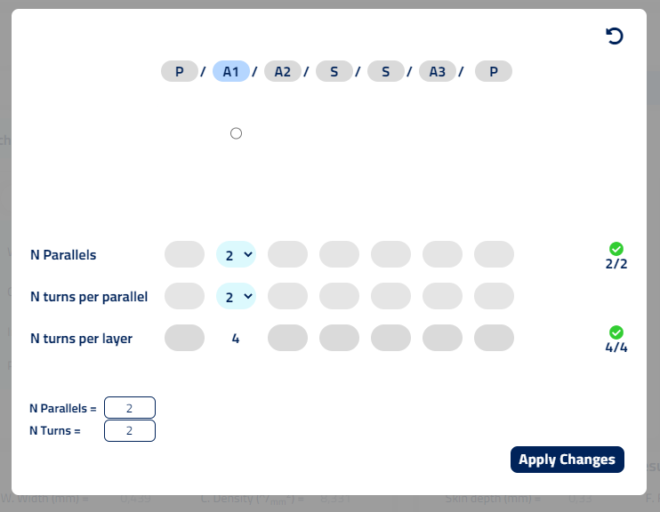
In the custom winding we have a table and a drawing of the winding. Each column of the table in the left refers to a layer in the drawing on the right.
The headers indicate the winding that conforms the given layer. In the example, the first layer "P" is filled with turns and parallels from the "Primary" winding, the second layer "A1" is filled with turns and parallels from "Auxiliar 1", the third layer, is filled with turns and parallels from the "Auxiliar 2", layer forth and fifth are filled with turns and layers from "Secondary" winding, etc etc.
Each layer has 4 cells in  and
and  .
.
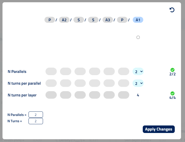
- N parallels. Input selector determine the number of parallels that are wounded on the layer for the given winding(shown on the headers)
- N turns per parallel. Input selector determine the number of turns that are wounded for each of the parallels on the layer.
- N turns per layer. The number of total turns that are located on the given layer. This number is computed automatically. For example; the second layer has two Auxiliar 1 parallels and has three turns wounded on each one of these parallels, therefore the number of total turns is 6, 3 turns per parallel.
- Connection between layers . Shown as small clickable circles. Input to indicate if the parallels on the layer end on the layer, or these are continued to be wounded in another layer. In the example, the second layer which is filled with turns and parallels from

What it is possible to do in this mode?
- Locate the layers of each windings in all possible arrangements
- Manage the number of parallels and turns that are winded per layer
- Manage connections between layers of the same winding
Locate the layers of each windings in all possible arrangements
For adjusting and customizing the layers of the windings it is only required to click and drag the headers of the layers and locate them on the desired position
Manage the number of parallels and turns that are winded per layer
Once the arrangement of all layers is defined, the distribution of parallels and turns per parallel for each layer can be determined.
For doing so a header of the winding that is deried to be modified is clicked. In the example there are two headers/layers for the Primary winding "P", two headers/layers for the Secondary "S" and one header/layers for each auxiliary "A1", "A2" and "A3".
After clicking a header of a winding:
- All the headers of the same winding will be highlighted.
- The total number of parallels and turns per parallel are shown on the bottom left corner.
- An additional "check" column appears to indicate if the actual selection complies with the requirements.

In this mode the two selectors "N Parallels" and "N turns per parallel" are available to select the desired configuration.
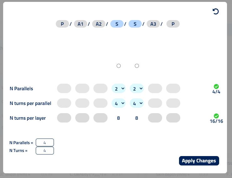
The unique requirement that must be fulfilled for the simulation to run, is that the N of Parallels and number of total turns of the winding are reached. These two values are determined in the winding section.
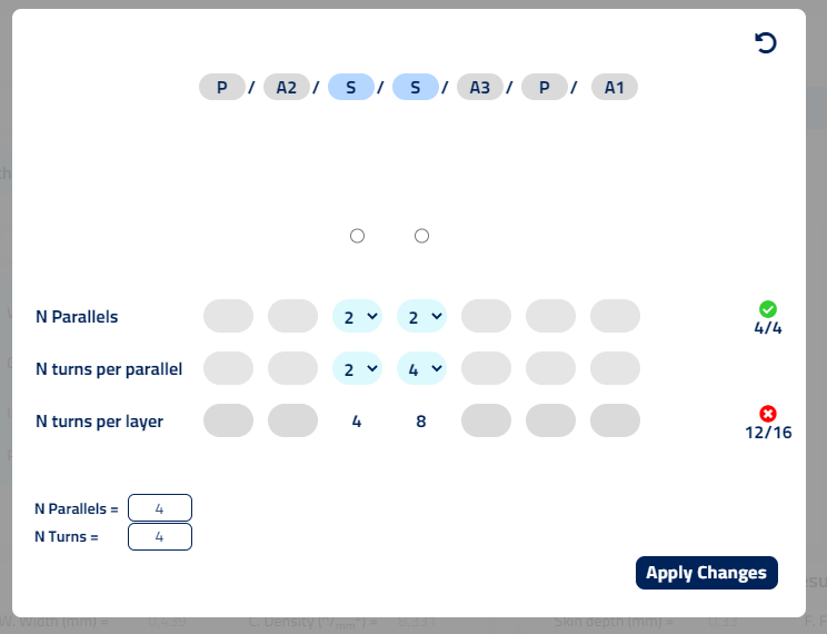
For ensuring so, the "check" column shows a green check in the rows where the requirement are achieved. And a red cross where any of these requirements are not fulfilled.
As it is seen in the following example, the secondary "S" has a total of 4 parallels, however 6 parallels are selected in the customizer, 4 parallels in the first layer and 2 on the second layer. The red crosses appears on the left indicating the unmatch in the sum of total parallels and total turns on the winding.

In the second example, although the number of parallels are reached, it is not the case for the total turns on the layer having 2 parallels with 2 turns each in one layer and 2 parallels with 4 turns each in the second layer.
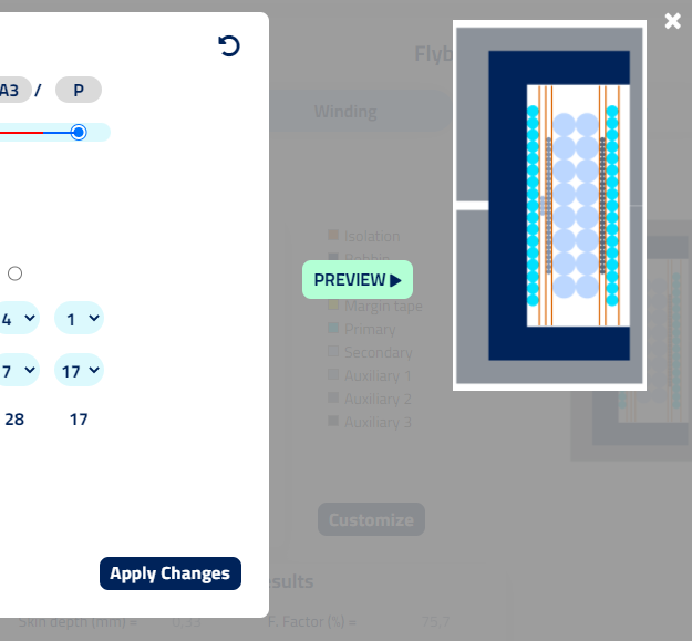
Once the "check" column shows both markers in green the "Apply Changes"  and "Preview"
  buttons will be available to click and process the information.
Manage connections between layers of the same winding
Besides the adjustment of the location of the different layers of the windings and the parallels and turns on them, the customization allows to determine when the parallels of the layers finish on the given layer, going to pin, or the parallels continue to be wounded in a different layer before going to pin.
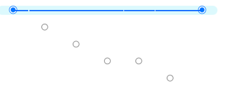
For connecting the paralells on two different layers of the same winding, the node section must be used.
For doing the connections the nodes of the layers must be used. For creating connections, only the nodes of the first and last layer have to be clicked. From left to right.


Once the connection is done, a blue line will unite all the nodes of the layers involved in the connection.
Once the parallels from two or more layers are connected, the "N Parallels" shall show the same number. This will affect the total N Parallels and therefore "check" column.
This effect is seen on the example. For allowing the changes to be applied the N turns per parallel and the N parallels shall be modified.

Preview and Apply Changes
Whenever the "Check" column shows the green check, the system will be able to "Preview" and to "Apply Changes".
- Preview recomputes the winding drawing with the last changes. Cause only the image and the dimensions of the magnetic are simulated, this process allows to do quick checkups to ensure the winding are fitting in the dimensions of the available window. If it is not the case, the software provides a warning besides the preview button.
- Apply Changes applies the changes introduced on the custom winding mode to the simulation. After the system computes all the outputs the rest of the sections of the simulator will be accesible again.
- Undo Changes, located above the check column, undo all changes and restores the last winding configuration that was processed after a "Run" or an "Apply changes".

- Close, located on the top right corner, undos the changes and returns to the simulation.
