Core
Overview
In the core section you will be able to select and define the parameters of your core, as well as seeing results of the simulation regarding Core losses and magnetic flux density.
At the top of the screen you will find several drop-down menus in blue, from which you will be able to define the parameters in order to characterize your core. These are:
- Technology:
 Choose between Ferrite or Powder cores.
 - Material:
 Select the material from the list.

Inductance - Launch Calculator
The Inductance Calculator can be accessed through the Launch Calculator button located in the Inductance section of the screen.
The calculator has two main modes:
Accurate Mode
The default. It computes the Inductance of the magnetic taking into consideration all constructive parameters and the operating conditions.

This mode is set by default once a simulation is created. It will compute the real inductance that the magnetic will show in the operation point once working on the converter.
For this Inductance computation, not only the geometrical and the electromagnetic properties of the selected core will be taken in to account. The whole system, including the ambient temperature, the current, the temperature on the magnetic produced due to core and winding losses, permeability, gaps distribution and fringing will be taken into consideration so the computed Inductance Value is as accurate as possible in the SOA.
In this mode the system takes all the parameters in the simulation, not only the ones in the core, but in the waveform and in the winding section. However, due to its influence and the common designing flows, the three main inputs are: The N (Primary Turns), N. Gaps (Number of gaps), Gap (Gap length for each gap).
Once these three (within the rest of the parameters in the simulation) are introduced, the new values for the L (Inductance), AL (Inductance Factor), FF (Fringing Factor) can be computed by clicking on the RUN button located on the bottom right corner of the screen.
Once it is clicked, the simulation will run and compute all the outputs of the simulation and the L (Inductance), AL (Inductance Factor), FF (Fringing Factor) that the magnetic will show in the given operating conditions.![]() The Apply button allows, once the selection and results satisfy the needs, to apply the changes within the rest of the simulation, return to the default mode and compute the simulation of the whole magnetic. If clicked, the simulation will run completely and some of the results may vary between modes.
The Apply button allows, once the selection and results satisfy the needs, to apply the changes within the rest of the simulation, return to the default mode and compute the simulation of the whole magnetic. If clicked, the simulation will run completely and some of the results may vary between modes.![]() On the other hand the Cancel button allows to undo all changes during this mode and return with the initial configuration on the Accurate Mode.
On the other hand the Cancel button allows to undo all changes during this mode and return with the initial configuration on the Accurate Mode.
Iteration Mode
It allows for fast iterations, changing the degrees of freedom between L (Inductance), N (Primary Turns), N. Gaps (Number of gaps) and Gap (Gap length for each gap).

By selecting different button modes in inductance calculator the degrees of freedom of the Inductance Calculator will change. In the Inductance Tab the main output will be the L, in N turns tab the main output will be N (Primary Turns) , and in Gap tab the main output will be the Gap (mm) length for each gap.
During this mode, no extra computations regarding the winding, losses or temperature will be carried out. Only the outputs of the inductance calculator will be processed, drastically reducing the time required to get the results and allowing fast iterations between different combinations. However, the shape and materials are also considered as inputs in this mode, so different alternatives can be explored.
Once this mode is selected, the desired output is chosen, and any value in the blue boxes is modified, the computations will be automatically triggered just by clicking somewhere else on the screen.
Gap Location
In addition to the above, it is also possible to determine the location of the Gap, wherever it is located in the center leg or in all the legs.
For modifying the location of the gap, the gap location selector is used.

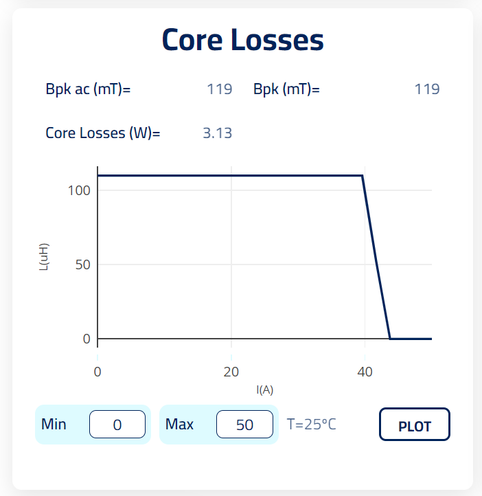
Core Losses
- Amplitude of the B field (Bpkac)
- Maximum working flux (BpkT)
- Core Losses
- Saturation Current at 25ºC and 100ºC
- Plotter:
 The Plotter is now integrated in the core page and automatically will draw the graph of Inductance against Current so you can see how the magnetic inductance changes in the selected current range. The current range is set automatically between 0 and the maximum current of your design but it can also be changed by hand to whatever range you would like to see.
To help clarify these outputs, a typical B-H curve for a Flyback transformer is shown in the image below:

Core parameters
At the top of this section you will find one or two drop-down menus in blue, from which you will be able to define the parameters in order to characterize your core. These are:
- Shape and size:
 Select the core shape and size from the list of standard cores available.
 - Datasheet:
 Click to access to the core specifications provided by the manufacturer.
 - Customize:
 The customize feature will allow you to modify any dimensions of the selected core. Click in the button and it will unlock the dimension fields , allowing you to type the new value for the specific dimension. Click anywhere in the screen or press enter to save the changes. To reset the dimensions click again the Customize button. The Core families that you will be able to edit are E, U, T (toroids) and PQ.
If the combination of core shape and material is not listed in the manufacturer's catalogue, a warning message will appear. You will still be able to simulate the design with the previous inputs.
Stacking cores and Custom dimensions features are only available for E and U shaped cores.
Stacking cores will allow to increase the Core area while keeping the same height and width.
Coil Former parameters
At the top of the screen you will find several drop-down menus in blue, from which you will be able to define the parameters in order to characterize your coil former. These are:
- Customize:
 The customize feature will allow you to modify any dimensions of the selected core. Click in the CUSTOM option and it will unlock the dimension fields , allowing you to type the new value for the specific dimension. Otherwise, you can choose the No coil option if your design does not require it. Toroids have only the "No coil" option.
 - Thickness:
 It is the coil former thickness (the coil former is considered to have the same wall thickness in all its shape). It should be bigger tan 0 mm. In practice a minium 0,5mm or 0,8 mm is recomended.
 - Coil Depth:
 It is the máximum length of the coil former. For custom coil formers it should be always bigger than the space required by the winding.
 - Distance to core:
 Distance between the core and the coil former. It is the air that exist between them. It should be bigger tan 0 mm.

Physical description 
In the right half of the screen you will be able to see the following information about your core.
- 3D model
- Plans
Run Core vs Run Core Only
At the bottom right there are two main buttons to trigger the simulation. The two options produce two type os simulations.
![]()
- Run Core Only:
 Triggers a quick simulation that only simulates the core constructive parameters within the given waveforms. No simulations will be done for the winding, impliyng that the results on the winding tab are likely to be outdated. Due to this absence of winding considerations a quicker simulation is provided making it a better simulation for trying out different types of configurations and iterations related with shapes, materials, inductances etc. However, it is important to bare in mind that the results provided; L, Bpkac, BpkT, AL, Core Losses, Total Losses, Temperature are simulated without the influence of the winding. The winding section can deeply determine the real behaviour of the core parameters, mainly through heat transfer, that the magnetic would have on the given operating conditions. This implies that, once the desired iterations in the core are finished, the run button should be clicked so a more accurate simulation is provided.

- Run:
 Triggers the full Frenetic Online simulation. It requires more time than in the previous case, but now, the output results are given by considering all the system, core and winding, impliying more accurate results. In this case the winding tab will be also updated.

Glossary
- L: Inductance shown on the primary winding of the magnetic.
- N: Number of turns on the primary winding of the magnetic.
- N.gaps: Number of gaps on the magnetic.
- Gap (mm): Length of each gap shown in the magnetic.
- Al: Inductar factor for the given shape, material, and gaps characteristics.
- FF: Fringing Factor that represents the the flux density spread on the gapped sections of the magnetic.